
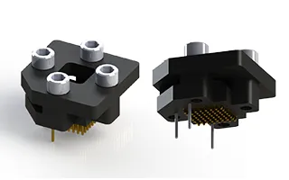
64-ball BGA/LGA socket, 0.8mm pitch, 8×8 grid, body 8×8mm.
SKU: XL0064XX0801F
XL0064XX0801F 64-Pin BGA/LGA Locking Socket – 0.80 mm Pitch, 8×8 Array
XL0064XX0801F is a precision-machined, footprint-compatible locking socket for 64-position BGA and LGA devices. The socket supports an 8×8 array at 0.80 mm pitch and an 8.0 × 8.0 mm device body. It mounts directly to the corresponding PCB device footprint, allowing installation, evaluation, programming, or replacement of the IC without redesigning the circuit board.
The low-profile socket is intended for prototype development, engineering evaluation, debugging, firmware development, failure analysis, and other limited-insertion applications. Typical socket service life is approximately 50–100 device insertion cycles, making it best suited for engineering and low-cycle use rather than high-volume production testing.
64-Pin BGA/LGA Socket Applications
The XL0064XX0801F 64-pin BGA/LGA socket provides a removable interface for compatible devices that would otherwise be soldered directly to the PCB. Typical applications include initial board bring-up, component evaluation, device programming, design verification, troubleshooting, firmware updates, and field replacement.
The 8×8, 0.80 mm pitch format may support compatible devices from semiconductor families such as Lattice iCE40, AMD Xilinx Spartan-7 CSGA64, and selected Microchip SAM devices. Package dimensions and ball assignments vary by device, so the IC package drawing should be reviewed before ordering. Additional package terminology and standards information is available from JEDEC.
Key Specifications
| Part Number | XL0064XX0801F |
|---|---|
| Package Interface | 64-position BGA or LGA |
| Array | 8 × 8 |
| Pitch | 0.80 mm |
| Device Body Size | 8.0 × 8.0 mm |
| Contact Array Size | 5.6 × 5.6 mm |
| Overall Socket Size | 15.15 × 15.15 mm |
| PCB Interface | Footprint-compatible |
| Termination Options | SMT or through-hole |
| Alignment Options | With or without alignment pins |
| Typical Service Life | 50–100 device insertion cycles |
| Contact Material | Brass Alloy C36000, ASTM B16, ½ hard |
| Insulator Material | FR4-G10 |
| Operating Temperature | -55°C to +140°C |
| Maximum Voltage | 75 VAC / 100 VDC |
| Maximum Current | 1 A per contact |
| Contact Resistance | 0.01 Ω maximum |
| Insulation Resistance | 10,000 MΩ minimum |
| Capacitance | 1 pF maximum |
Features and Benefits
- Fits the corresponding 64-position BGA or LGA PCB footprint
- Eliminates the need to redesign the PCB for socket installation
- Allows compatible devices to be installed and removed without repeated PCB rework
- Low-profile, screw-locking construction
- Available with BL or LL pogo contact configurations
- SMT and through-hole termination options
- Available with or without PCB alignment pins
- Custom package footprints and configurations available
BL and LL Contact Options
- BL — Standard pogo plunger contact configuration
- LL — Alternate pogo plunger contact configuration
BL and LL versions use the same base footprint and mechanical envelope but differ in contact style. Specify the preferred series, termination method, and alignment-pin option when requesting a quotation.
Engineering Review and Ordering
All XL Series sockets are built to order, with a typical lead time of two to four weeks. Before ordering, provide the complete IC package drawing or manufacturer datasheet so Adapters-Plus can verify body dimensions, array geometry, pitch, ball pattern, and mechanical compatibility.
Contact Adapters-Plus to request a quotation or engineering review. Additional dimensions, ordering information, materials, and electrical ratings are available in the XL0064XX0801F datasheet. You can also review our IC test socket solutions for applications requiring different package formats or higher insertion-cycle capability.
Related Products
-

324-ball BGA/LGA socket, 0.8mm pitch, 18×18 grid, body 15×15mm.
324-ball BGA/LGA socket, 0.8mm pitch, 18×18 grid, body 15×15mm.
324-ball BGA/LGA socket, 0.8mm pitch, 18×18 grid, body 15×15mm. Footprint-compatible. Ideal for prototyping, development, and functional production testing. Quote request only.
-

484-ball BGA/LGA socket, 1mm pitch, 22×22 grid, body 23×23mm.
484-ball BGA/LGA socket, 1mm pitch, 22×22 grid, body 23×23mm.
484-ball BGA/LGA socket, 1mm pitch, 22×22 grid, body 23×23mm. Footprint-compatible. Ideal for prototyping, development, and functional production testing. Quote request only.
-

388-ball BGA/LGA socket, 1.27mm pitch, 26×26 grid, body 35×35mm.
388-ball BGA/LGA socket, 1.27mm pitch, 26×26 grid, body 35×35mm.
388-ball BGA/LGA socket, 1.27mm pitch, 26×26 grid, body 35×35mm. Footprint-compatible. Ideal for prototyping, development, and functional production testing. Quote request only.
-

676-ball BGA/LGA socket, 1mm pitch, 26×26 grid, body 27 × 27mm.
676-ball BGA/LGA socket, 1mm pitch, 26×26 grid, body 27 × 27mm.
676-ball BGA/LGA socket, 1mm pitch, 26×26 grid, body 27 × 27mm. Footprint-compatible. Ideal for prototyping, development, and functional production testing. Quote request only.
-

676-ball BGA/LGA socket, 1.27mm pitch, 26×26 grid, body 35×35mm.
676-ball BGA/LGA socket, 1.27mm pitch, 26×26 grid, body 35×35mm.
676-ball BGA/LGA socket, 1.27mm pitch, 26×26 grid, body 35×35mm. Footprint-compatible. Ideal for prototyping, development, and functional production testing. Quote request only.
-

900-ball BGA/LGA socket, 1mm pitch, 30×30 grid, body 31 × 31mm.
900-ball BGA/LGA socket, 1mm pitch, 30×30 grid, body 31 × 31mm.
900-ball BGA/LGA socket, 1mm pitch, 30×30 grid, body 31 × 31mm. Footprint-compatible. Ideal for prototyping, development, and functional production testing. Quote request only.
-

1156-ball BGA/LGA socket, 1mm pitch, 34×34 grid, body 35×35mm.
1156-ball BGA/LGA socket, 1mm pitch, 34×34 grid, body 35×35mm.
1156-ball BGA/LGA socket, 1mm pitch, 34×34 grid, body 35×35mm. Footprint-compatible. Ideal for prototyping, development, and functional production testing. Quote request only.
-

1020-ball BGA/LGA socket, 1mm pitch, 32×32 grid, body 33×33mm.
1020-ball BGA/LGA socket, 1mm pitch, 32×32 grid, body 33×33mm.
1020-ball BGA/LGA socket, 1mm pitch, 32×32 grid, body 33×33mm. Footprint-compatible. Ideal for prototyping, development, and functional production testing. Quote request only.
-
1024-ball BGA/LGA socket, 1.27mm pitch, 32×32 grid, body 45×45mm.
1024-ball BGA/LGA socket, 1.27mm pitch, 32×32 grid, body 45×45mm.
1024-ball BGA/LGA socket, 1.27mm pitch, 32×32 grid, body 45×45mm. Footprint-compatible. Ideal for prototyping, development, and functional production testing. Quote request only.
-

96-ball BGA/LGA socket, 0.8mm pitch, 6×16 grid, body 5.5×13.5mm.
96-ball BGA/LGA socket, 0.8mm pitch, 6×16 grid, body 5.5×13.5mm.
96-ball BGA/LGA socket, 0.8mm pitch, 6×16 grid, body 5.5×13.5mm. Footprint-compatible. Ideal for prototyping, development, and functional production testing. Quote request only.