
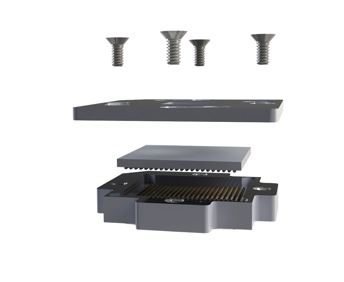
XL Series BGA & LGA Locking Test Sockets
Machined locking sockets for BGA and LGA devices — footprint-compatible and built to order for your PCB land pattern.
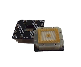
Overview
The XL Series is a family of machined locking test and burn-in sockets designed for BGA and LGA device packages. BL Series sockets target BGA devices; LL Series sockets target LGA devices. Both variants share the same mechanical architecture and mount directly to existing PCB land patterns without requiring board modifications.
Standard configurations support 0.80 mm, 1.00 mm, and 1.27 mm pitches, covering packages from low pin-count MCUs to arrays exceeding 1,500 contacts. Because each socket is built to order, footprint dimensions, contact style, and mechanical clearance are matched to the target board at the time of quote.
Available Configurations
Standard configurations are listed below. Contact us to request a quote or discuss a custom footprint.
| No. | Base P/N | Pin Count | Pitch (mm) | Array | Body X (mm) | Body Y (mm) | Supported Devices |
|---|---|---|---|---|---|---|---|
| 1 | XL0064XX0801F | 64 | 0.8 | 8X8 | 8 | 8 | Lattice iCE40, Xilinx Spartan-7 csga64, Microchip SAML |
| 2 | XL0081XX0901F | 81 | 0.8 | 9X9 | 8 | 8 | Lattice ECP5, Microchip SmartFusion, NXP i.MX |
| 3 | XL0081XX0904F | 81 | 1 | 9X9 | 10 | 10 | Xilinx Spartan-6 cpg, TI Sitara, MCU families |
| 4 | XL0100XX1002F | 100 | 0.8 | 10X10 | 10 | 10 | Lattice ECP5-12, Altera MAX 10, Microchip PIC32 |
| 5 | XL0100XX1005F | 100 | 1 | 10X10 | 11 | 11 | Xilinx Spartan-6, Altera Cyclone II |
| 6 | XL0121XX1103F | 121 | 0.8 | 11X11 | 10 | 10 | Xilinx Spartan-7 csga144, Lattice ECP5-17 |
| 7 | XL0144XX1205F | 144 | 0.8 | 12X12 | 10 | 10 | Lattice ECP5-25, Xilinx Spartan-7 cpga144, Artix-7 |
| 8 | XL0144XX1204F | 144 | 1 | 12X12 | 13 | 13 | Xilinx Spartan-6 cpg144, Altera Cyclone III/IV |
| 9 | XL0169XX1307F | 169 | 0.8 | 13X13 | 11 | 11 | Lattice ECP5-25, Xilinx Artix-7 csg324 |
| 10 | XL0196XX1413F | 196 | 0.8 | 14X14 | 12 | 12 | Lattice ECP5-25F, Altera Cyclone V |
| 11 | XL0196XX1408F | 196 | 1 | 14X14 | 15 | 15 | Altera Cyclone IV EP4CE22, Intel Cyclone 10 |
| 12 | XL0256XX1614F | 256 | 0.8 | 16X16 | 14 | 14 | Xilinx Spartan-7, Artix-7, Zynq-7010 cs400 |
| 13 | XL0256XX1611F | 256 | 1 | 16X16 | 17 | 17 | Xilinx Spartan-6, Artix-7, Altera Cyclone IV GX |
| 14 | XL0324XX1802F | 324 | 1 | 18X18 | 19 | 19 | Altera Cyclone IV, Microchip PolarFire, Intel 10M50 |
| 15 | XL0324XX1809F | 324 | 0.8 | 18X18 | 15 | 15 | Xilinx Artix-7, Zynq-7010 clg400 |
| 16 | XL0484XX2205F | 484 | 1 | 22X22 | 23 | 23 | Xilinx Kintex-7, Artix-7 fbg484, Zynq-7020 |
| 17 | XL0388XX2607F | 388 | 1.27 | 26X26 | 35 | 35 | Xilinx Virtex-4/5, older Altera Stratix |
| 18 | XL0676XX2623F | 676 | 1 | 26X26 | 27 | 27 | Xilinx Kintex-7, Zynq-7045, Artix-7 fbg676 |
| 19 | XL0676XX2624F | 676 | 1.27 | 26X26 | 35 | 35 | Xilinx Virtex-5/6, Altera Stratix III/IV |
| 20 | XL0900XX3006F | 900 | 1 | 30X30 | 31 | 31 | Xilinx Kintex UltraScale, Virtex-7 fbg900 |
| 21 | XL1156XX3406F | 1156 | 1 | 34X34 | 35 | 35 | Xilinx Virtex UltraScale ffg1156, Kintex UltraScale |
| 22 | XL1020XX3203F | 1020 | 1 | 32X32 | 33 | 33 | Networking ASICs, Broadcom, Marvell, NXP QorIQ |
Need Technical Guidance?
Share your BGA or LGA package drawing along with board constraints such as keep-out zones, height limits, or nearby components. Include pitch, ball or land count, and your preferred mounting approach.
Mounting Configurations
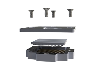
Surface Mount (SMT)
The XL Series mounts directly to an existing BGA or LGA footprint via SMT solder balls. This is the standard low-profile configuration for boards where component clearance is not a constraint.
- Typical clearance above PCB: ~0.060″
- Compatible with standard reflow processes
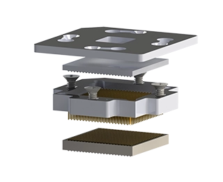
Through-Hole with FBS Receptacle
For boards with dense component layouts or where socket serviceability is required, the XL Series can be configured with through-hole tails and mated to an FBS Series BGA Socket Receptacle. The FBS receptacle solders permanently to the PCB; the XL socket plugs in and can be removed without rework.
- Typical clearance above PCB: ~0.130″
- Additional clearance available with stacking adapters (~0.130″ per stage)
Features & Benefits
- Direct Footprint Compatibility: Mounts to existing BGA and LGA PCB land patterns — no board modifications required.
- BGA and LGA Support: BL Series for BGA devices; LL Series for LGA devices. Both use the same socket architecture and footprint.
- Development Through Production: Common socket design supports bench validation, functional test, and burn-in on the same hardware.
- Locking Mechanism: Positive device retention ensures repeatable contact engagement across test cycles.
- Built to Order: Contact style, termination, and footprint details configured to match your PCB at time of quote.
- Expandable Clearance: Through-hole variant mates with FBS Series receptacle for increased board clearance and field-replaceable socket assemblies.
Typical Performance Specifications
Performance characteristics are based on standard XL Series locking test socket
configurations. Final specifications may vary depending on the selected contact
system, package configuration, and application requirements.
| Category | Specification | Typical Value |
|---|---|---|
| Electrical | Maximum Voltage | 75 VAC / 100 VDC |
| Electrical | Maximum Current | 1.0 A per contact |
| Electrical | Contact Resistance | 0.01 Ω max |
| Electrical | Insulation Resistance | 10,000 MΩ min @ 500 VDC |
| Electrical | Capacitance | 1 pF max |
| Electrical | Self Inductance | 2 nH max |
| Thermal | Operating Temperature | -55°C to 140°C |
| Thermal | Resistance to Soldering Heat | 10 seconds @ 288°C |
| Thermal | Flammability Rating | UL94V-0 |
| Materials | Contacts | Brass Alloy C36000 (ASTM-B16), 1/2 Hard |
| Materials | Insulator | FR4-G10 |
If your application requires enhanced electrical performance, higher current
capacity, specialized materials, or other custom requirements, Adapt-Plus can
configure an XL Series locking test socket to meet your specific engineering
and production objectives.
Need Technical Guidance?
Every XL Series locking test socket is built to order for the target device and PCB footprint. If you’re unsure which configuration is required, our engineering team can review your application and recommend the appropriate socket design.
To begin the quotation process, provide your BGA or LGA package drawing, device pitch, ball or land count, PCB land pattern, keep-out zones, height restrictions, and preferred mounting configuration. We’ll review your requirements and recommend the appropriate XL Series socket for your application.